19 Aug Pushing the Limits: Redefining Inverter Clipping
 Have you ever noticed the rating of an inverter connected to a PV (Photovoltaics) array? Was the rating of the inverter lower than the capacity of the PV array, making DC (Direct Current)/AC (Alternating Current) ratio bigger than one? These pressing questions on inverter sizing often mystify people, but this article will help you to understand clipping losses, their importance, and how to manage them effectively.
The short answer for this rating difference between the DC and AC sides of a PV system is the management of clipping losses by considering the financial aspects for the customer.
What is a clipping loss? How does it occur? Alternatively, what will happen if we connect a 6kW inverter to an 8kW DC system?
If the input DC power of an inverter is higher than the handling capacity of the inverter or its nameplate rating, then the inverter will only convert the DC to AC power up to its nameplate rating. The remaining extra DC input power to the inverter will be lost or clipped, which is also termed as the “clipping loss” in an inverter. To understand practically, let us take an example. Suppose if we have a 6kW inverter connected to an 8kW of DC PV system and imagine if it is a bright sunny day with an ambient temperature equal to 77° F (or 25°C) during a day. Then the PV system will generate up to its rated power output of 8kW DC until the system operates at the STC conditions (Standard Test Condition with Temperature 25°C, Solar Irradiance – 1000 Watts per square meter and Air Mass index – 1.5). The 8kW DC generated power output will become an input for the inverter, but due to the rated capacity of the inverter, the inverter will only convert 6kW of DC to AC power, and the remaining 2kW of DC power will be lost. Meaning, that the inverter will only convert DC to AC power until its saturation level, and this saturation of the inverter is termed as “clipping”, which occurs when the input power of an inverter is higher than the rated capacity of the inverter.
Now, the question is, if we are losing power in terms of clipping loss, then why not use an inverter of the same rating as the DC output of the PV system. For instance, an 8kW inverter connected with an 8kW DC PV array?
There are multiple factors which strike the power output of a PV array, and ‘Temperature’ is one of the paramount factors. A PV array works on its rated capacity when the surrounding conditions are equal to the STC conditions. Although, the STC condition occurs for a short interval during the whole day. As the temperature crosses 25°C for the surface of the panel, then the DC output of the array starts decreasing linearly. This decrease in power production depends on the temperature coefficient (temperature coefficient depends on the manufacturing material of the module), which is always provided by the panel manufacturer. Except the winter season, for most of the duration in a day, the temperature remains higher than the 25°C. As stated above, temperatures above 25°C act as a limiting factor and restrict the PV array to achieve its rated capacity.
In the above example, for the same reason, the 8kW PV array will produce less than its rated capacity for most of the time during the day. Another interesting point, that we will have 0% clipping losses if we connect an 8kW inverter to an 8kW PV array but, the inverter will be operating below its saturation level for most of the time because of the temperature greater than 25°C during the day. As explained above, ambient temperature higher than 25°C will reduce dc output of the PV array. Figure 1 represents the average clipping losses and usable energy for different months with a system size of 7.47kW. The upper yellow section in figure 1 represents the lost energy in terms of clipping loss.
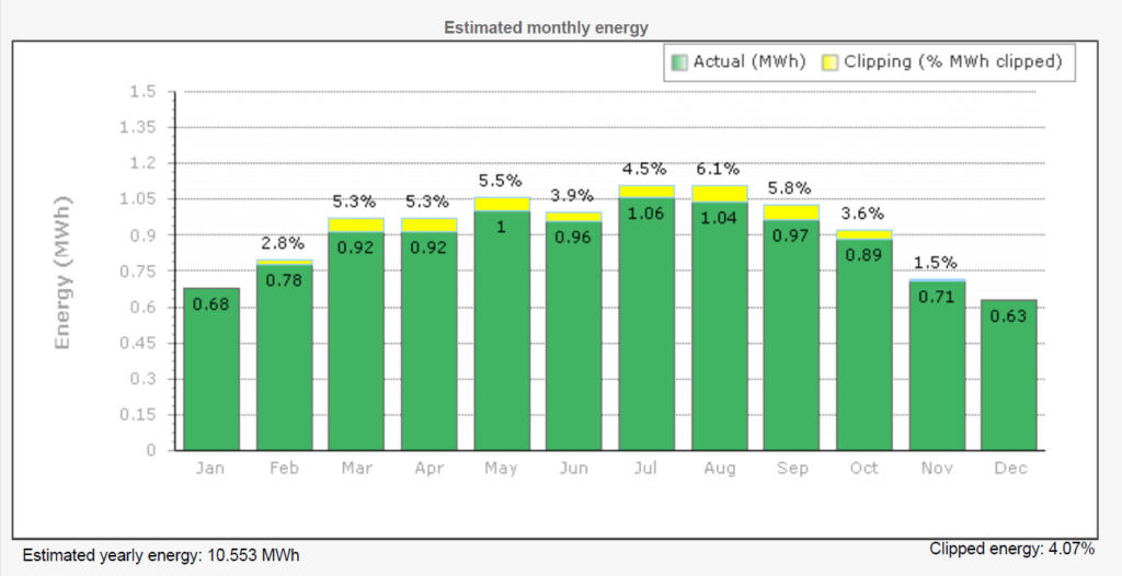
Figure 1: Annual energy production for an example site with usable energy represented by the green color and clipped energy represented by the yellow color.
Now the question arises for sizing the inverter. AC/DC ratio can be adjusted in between to maximize the utilization of the inverter, designers prefer to oversize the PV array by a factor of 1.1 to 1.5. This oversizing factor is also known as the DC/AC ratio. Instead, we can say that a 7.6kW capacity inverter can handle from 8.36 to 11.4kW of DC with DC/AC ratio between 1.1 to 1.5. Companies are continuously working to improve the DC/AC ratio for inverters, and recently, SolarEdge has introduced Energy Hub Inverters which can be oversized up to 200%. To finalize the inverter size, designers can use different simulation tools like Helioscope and Aurora to analyze clipping losses, and 0-3% of clipping losses are acceptable.
Inverters run most efficiently when running at or near their maximum capacity. If a solar array is not likely to reach that maximum capacity majority of the time, that’s when clipping comes into play. If the inverter is rated lower than the system, it may actually be operating more efficiently and cost effectively than if it were rated at the same size of the solar array. So, long story short oversizing the inverter is not a requirement. It is a trade-off between power production and economics as reducing inverter size will also help the customer financially and maximize the utilization of inverters.
Researched and written by: Madhukar Dadhich, Engineering Intern
Sorry, the comment form is closed at this time.